Using a quadrature encoder as input to FPGA
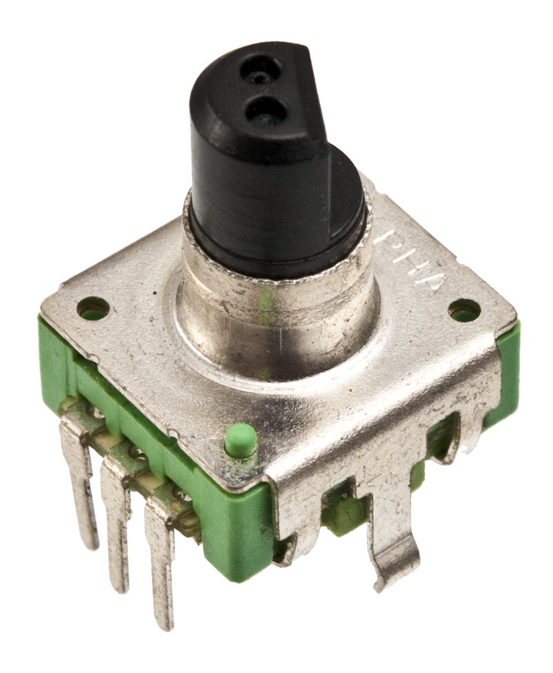
This time, instead of using buttons to control the servo, we will use a quadrature encoder (I got it from Sparkfun, sku: COM-09117, but you should be able to use more or less any quadrature encoder).
The QuadratureDecoder entity
This entity reads the signals from the quadrature encoder and maintains a counter, that is incremented or decremented depending on which way the knob is rotated.
The VHDL below is more or less a translation of the Verilog example at fpga4fun.com, where you can also find a description of the signals from the quadrature encoder.
library IEEE;
use IEEE.STD_LOGIC_1164.ALL;
use IEEE.STD_LOGIC_ARITH.ALL;
use IEEE.NUMERIC_STD.ALL;
use IEEE.STD_LOGIC_UNSIGNED.ALL;

entity QuadratureDecoder is
    Port ( QuadA : in  STD_LOGIC;
           QuadB : in  STD_LOGIC;
           Clk : in  STD_LOGIC;
           Position : out  STD_LOGIC_VECTOR (7 downto 0));
end QuadratureDecoder;

architecture Behavioral of QuadratureDecoder is

signal QuadA_Delayed: unsigned(2 downto 0) := "000";
signal QuadB_Delayed: unsigned(2 downto 0) := "000";

signal Count_Enable: STD_LOGIC;
signal Count_Direction: STD_LOGIC;

signal Count: unsigned(7 downto 0) := "00000000";

begin

process (Clk)
begin
	if Clk='1' and Clk'event then
		QuadA_Delayed <= (QuadA_Delayed(1), QuadA_Delayed(0), QuadA);
		QuadB_Delayed <= (QuadB_Delayed(1), QuadB_Delayed(0), QuadB);
		if Count_Enable='1' then
			if Count_Direction='1' then
				Count <= Count + 1;
				Position <= conv_std_logic_vector(Count, 8);
			else
				Count <= Count - 1;
				Position <= conv_std_logic_vector(Count, 8);
			end if;
		end if;
	end if;
end process;

Count_Enable <= QuadA_Delayed(1) xor QuadA_Delayed(2) xor QuadB_Delayed(1)
				xor QuadB_Delayed(2);
Count_Direction <= QuadA_Delayed(1) xor QuadB_Delayed(2);

end Behavioral;
Modified version of the top module
This is the same top module as used with the previous post, but with the button controller exchanged with the above quadrature decoder.
library IEEE;
use IEEE.STD_LOGIC_1164.ALL;
use IEEE.STD_LOGIC_ARITH.ALL;
use IEEE.NUMERIC_STD.ALL;
use IEEE.STD_LOGIC_UNSIGNED.ALL;

entity ServoUpDown is
    Port ( Clk : in  STD_LOGIC;
           QuadA : in STD_LOGIC;
           QuadB : in STD_LOGIC;
           Servo : out  STD_LOGIC);
end ServoUpDown;

architecture Behavioral of ServoUpDown is

signal Position : std_logic_vector (7 downto 0);

begin

Servo1: entity ServoDriver port map (Clk, Position, Servo);
QuadDecoder1: entity QuadratureDecoder port map (QuadA, QuadB, Clk, Position);

end Behavioral;
The modified UCF file for the AVNET Xilinx® Spartan®-3A Evaluation Kit
Here I just removed the two buttons and added the two inputs from the quadrature encoder. To keep it simple on the hardware side, I enabled pull-up on both of those I/O’s, and connected the shared pin from the quadrature encoder to GND on the board. The servo is connected with negative to GND, positive to +5v and signal to D10.
#Created by Constraints Editor (xc3s400a-ft256-4) - 2010/06/17
NET "Clk" TNM_NET = "Clk";
TIMESPEC TS_Clk = PERIOD "Clk" 62.5 ns HIGH 50 %;

# PlanAhead Generated physical constraints
NET "Clk" LOC = C10;
NET "Servo" LOC = D10;
NET "QuadA" LOC = C5;
NET "QuadB" LOC = C6;

# PlanAhead Generated IO constraints
NET "Clk" IOSTANDARD = LVCMOS33;
NET "Servo" IOSTANDARD = LVCMOS33;
NET "QuadA" IOSTANDARD = LVCMOS33;
NET "QuadB" IOSTANDARD = LVCMOS33;

# PlanAhead Generated IO constraints
NET "QuadA" PULLUP;
NET "QuadB" PULLUP;
Below is a video showing the use of the quadrature encoder to control the servo position